Enigma and the Bombe
Lecture by Tony Sale

Tony Sale's
Codes and Ciphers
Enigma and the BombeLecture by Tony Sale | Tony Sale's Codes and Ciphers |
| This page is in the form of Lecture Notes and has not been fully edited for Web publication. |
The mathematician Alan Turing had been identified, at Cambridge, as a
likely candidate for code breaking. He came to the Government Codes &
Ciphers School, (GC&CS), in Broadway in London a number of times in
early 1938 to be shown what had already been achieved. He was shown
the rodding method and some intercepts of German signals enciphered
on the German forces Enigma which had the stecker board. Dilly Knox
already knew that the German forces Enigma rotors were wired differently
to the commercial rotors, did not know the entry rotor order and
apparently did not know of the double encipherement of the message key.
Turing began, independently, to discover the same characteristic patterns
as Rejewski discovered but Turing's were based on possible German words
from which the intercepted cipher text had been produced rather than
the repeated message key which Rejewski used.
An early method for decoding Enigma messages was called "Rodding".
It is described in Turing's "Treatise on Enigma" which he wrote, probably
in 1940.
Turing's description is not very clearly written, but after a considerable
amount of effort it can now be demonstrated.(in a paper still to be completed)
Rodding is basically a paper method involving representing the Enigma
wheels by strips of paper or card. Turing called these "comic strips".
A colour coding was used to identify the Enigma wheels.
The method based on probable words was a far more powerful method than
Rejewski's and led later to the development of the Turing Bombe.
GC&CS already had a few intercepts and at least one plain text / ciphertext
pair, reputed to have been smuggled to England by a Polish cipher clerk.
Among the characteristics that Turing had found was that occasionally the
same cipher/plain text pair of characters occurred at different places in
the same message. These were known as "clicks" in Bletchley Park.
.....JYCQRPWYDEMCJMRSR
Remember that because the Enigma machine is reversible, R->C is the same
as C->R and M->E the same as E->M.
Whether such pairings occur is determined by the rotor order and the core
rotor start positions. Turing realised that conversely the actual rotor
order and core rotor start position could be arrived at by trying all
configurations to see if these pairings were satisfied. This would only work
for an unsteckered Enigma or for a Steckered Enigma in which C and R were
unsteckered. In the early days of Enigma, only six letters were Steckered
so this could happen.
Obviously just setting up a single Enigma machine and trying by keying in
would take an impossibly long time. The next step was to consider how the
tests could carried out simultaneously for a particular Enigma start
configuration.
Testing for letter pairs required a method for rapidly determining whether
such a configuration was true or false. This led to the concept of
electrically connecting together a number of Enigma machines.
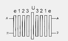
This was achieved by using an "opened out" Enigma.
In the actual Enigma electrical current enters and leaves by the fixed
entry rotor because of the reflector or Umkerwaltz (U) and this precluded
connecting Enigmas together. In Turing's opened out Enigma the reflector
had two sides, the exit side being connected to three rotors representing
the reverse current paths through the actual Enigma rotors. This gave
separate input and output connections and thus allowed a number of Enigmas
to be connected in series.
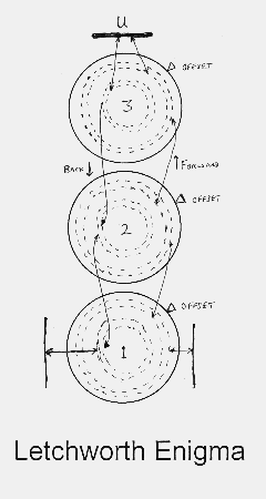
In the Letchworth (so called because the British Tabulating Machine factory
which made them was in the town of Letchworth), implementation, the clever
thing was to include both forward and backward wiring of an Enigma rotor
in one drum. The connections from one drum to the next were by four
concentric circles of 26 fixed contacts and four concentric sets of wire
brushes on the drum. Three sets of fixed contacts were permanently wired
together and to the 26 way input and output connectors. Three drums,
representing the original Enigma rotors, could now be placed on shafts
over the contacts and this was an opened out Enigma with separate input
and output connectors.
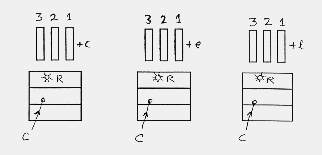
To return to the problem of checking whether C enciphers to R, ( written
as C->R ), first an offset reference from the start is required. A lower
case alphabet written over the cipher text gives this.
.....abcdefghijklmnopq
This shows that C->R at offset c, e and l from the start and M->E
at j, k and n. The opened out Enigma allows an electric voltage to be
applied to the input connection "C" and a set of 26 lamps to be connected
to the output connector. If the R lamp lights then the drums are in an
order and position such that C enciphers to R.
With a single Enigma this can occur at a vast number of drum settings.
However the crib allows an opened out Enigma to be set up for each
occurrence of C->R and they can all be tested simultaneously.
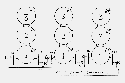
The opened out Enigmas are all set up with the same drum order and
the drums are then turned to the same settings for the top (left hand)
and middle drums but the bottom (right hand) drums are turned to the
offset letter along the crib at which the test is to be made. All the
inputs are connected in parallel and a voltage applied to the "C" contact.
Then a set of relays connected to each of the "R" output contacts tests
to see if all the R contacts have a voltage on at the same time.
When they do a position of the drums has been found which satisfies the
crib at the points chosen for C->R.
If they don't then all the bottom drums are advanced one position and
the test is tried again. After 26 positions of the bottom drum the centre
drum is advanced one position and this continues until all drum positions
have been tested. Then the drums are changed to try a different drum order.
A very long process by hand which obviously asks to be automated.
But there are still a large number of positions which satisfy the C->R test.
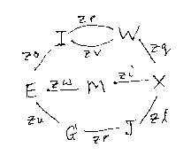
An extension of the concept of letter pairs is where letters enciphered
from one to another at different places in the crib resulting in loops of
letters.
.....abcdefghijklmnopq
For instance R->N at g, N->S at p and S->R at q making a loop.
A diagram showing such loops was known as a menu.
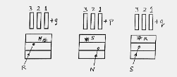
But if Steckers are being used this is actually
R Steckered to S1 enciphers to S2 Steckered to N at g,
N Steckered to S2 enciphers to S3 Steckered to S at p,
S Steckered to S3 enciphers to S1 Steckered to R at q.
The problem now is to find the core positions S1, S2 and S3.
If these can be found then they are the Steckers of the menu letters.
But Turing realised that there was another way of looking at interconnected
opened out Enigmas and that this way found Stecker connections.
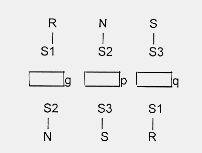
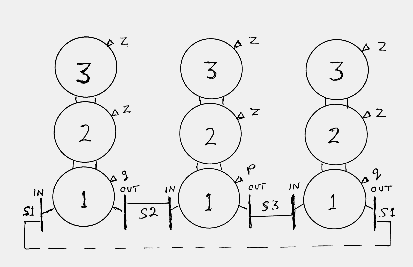
Take the loop example above of R->N->S->R. Three opened out Enigmas
are connected serially one to the other and the bottom drums are turned to
the offsets g, p and q. If the correct drum order is being used then there
will be some start position of the top, middle and bottom drums which
corresponds to the actual original Enigma core rotor positions having
allowed for the difference between the original Ringstellung and ZZZ.
At this point the core rotor positions will be the same as the original
Enigma core rotor positions and the encipherements will then be the same.
This means that a voltage placed onto the S1 input of the first opened
out Enigma, which is the Stecker of the input R, will come out on the
S2 terminal which is the Stecker of N. Since this is connected to the
next opened out Enigma, this goes in on its S2 terminal and comes out
on the S3 terminal which is the Stecker of S. This S3 input now goes
through the third opened out Enigma and comes out at S1 which is the
Stecker of R. Thus the drum positions correspond to the original Enigma
positions where S1->S2->S3->S1.
The magic trick is now to connect the output terminals of the last opened
out Enigma back to the input of the first Enigma. There is now a physical
wired connection through the opened out Enigmas from the S1 input terminal
to the S1 output terminal which is now connected to the S1 input terminal.
This forms a loop of wire not connected to any other terminals on any opened
out Enigma.
Thus if a voltage is placed on S1 at the input it goes nowhere else, just
appears on the S1, S2 and S3 terminals. If a strip of 26 lamps is connected
at the joins between opened out Enigmas then the S1, S2 and S3 lamps will
light confirming the voltage path through S1, S2 and S3.
Now comes Turing's really clever bit. If S1 is not known and the voltage
is placed on, say, A then this voltage will propagate through the opened
out Enigmas because they are joined around from output to input, but CANNOT
reach the S1, S2, S3 loop because it is not connected to any other
terminals. The voltage runs around the wires inside the opened out Enigmas
until it reaches a terminal which already has the voltage on it.
The complete vastly complex electrical network has then reached a steady
state.
Now if the lamp strip is connected at the joins of the opened out Enigmas,
lots of lamps will light showing where the voltage has reached various
terminals, but the appropriate S1, S2 and S3 lamps will not light.
In favourable circumstances 25 of the lamps will light. The unlit lamp
reveals the core letters, S1, S2 or S3. These are interpreted as the
Steckers of the letters on the menu.
When the drum order and drum positions are correct compared to that of
the original core Enigma encipherement there is just the one wired
connection through the opened out Enigmas, at connections S1, S2 and S3.
But Turing also realised that such a system of joined opened out Enigmas
could rapidly reject positions of the drums which were not the correct
ones.
If the drums are not in the correct position then the loop S1, S2, S3
does not exists and the voltage can propagate to these terminals as well.
Thus it is possible for the voltage to reach all 26 terminals at the join
of two of the opened out Enigmas. This implies that there is no possible
Stecker letter and therefore this position of the drums cannot be correct.
But because of the way the cross wiring inside real Enigma rotors is
organised, closed loops of connections can occur which are not the loops
corresponding to the actual Stecker connections being looked for.
The configuration of opened out Enigmas cannot distinguish between these
spurious loops and the correct Stecker loop.
The test for a loop of possible Steckers at a particular drum order and
rotor position is to see if either only one or 25 of the lamps are lit.
If all 26 lamps light then this position can be rejected and this
rejection can occur at very high speed. The voltage flows around the
wires at nearly the speed of light so that the whole complex network
stabilises in fractions of a microsecond. What was required was some
way of automating the changes of drum position for all the drums in
synchronism and for rapidly sensing any reject situation.
In 1939 the only technology available for achieving electrical connections
from rapidly changing drum positions was to use small wire brushes on
the drums to make contact with fixed contacts on the Test Plate. This
was a proven technology from punched card equipment. High speed relays
were initially the only reliable devices for sensing the voltages on the
interconnections. Thermionic valves were tried but were not reliable
enough in 1939. Later, thyratron gas filled valves were used successfully
and these were about 100 times faster than the high speed relays.
The British Tabulating Machine Co (BTM) had designed the opened out Enigmas
and built the Test Plate. The project to now build a complete search engine,
which became known as a Bombe, came under the direction of H H (Doc) Keen.
The machine, known as Victory, was completed by March 1940 and delivered to
Bletchley Park. It was first installed in one end of Hut 1. Now the work
began on finding out how to use this new device. Results at first were not
very encouraging. The difficulties in finding cribs meant that when a menu
was constructed between intercepted enciphered text and a crib, it usually
did not have enough loops to provide good rejection and therefore a large
number of incorrect stops resulted.
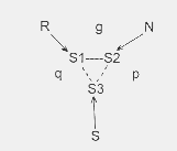
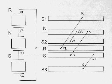
Then Gordon Welchman came up with the idea of the diagonal board. This was
an implementation of the simple fact that if B is Steckered to G then G
is also Steckered to B. If 26 rows of 26 way connectors are stacked up,
then any connection point can be referenced by its row letter and column
letter. A physical piece of wire can now connect row B element G to row G
element B. The device was called a Diagonal Board because such a piece of
wire is diagonally across the matrix of connections.
Now the double ended Enigma configuration knows nothing about Steckers.
It can only deduce rotor core wiring positions which satisfy the menu.
However the possible Steckers such as R<->S1, can by exploited by the
Diagonal Board. If the joins between double ended Enigmas are also
connected into the Diagonal Board at the position corresponding to the
original cipher / plain text pair on the menu, say R, then this can
significantly increase the rejection of incorrect double ended Enigma
drum positions.
It has already been shown that if a set of drum positions has been found
where S1->S2->S3->S1 then a physical wired connection has been made through
the joins between opened out Enigmas at S1, S2 & S3. The deduction from
this is that R is Steckered to S1 etc. Now if the join representing R on
the menu is plugged to the R row of the Diagonal Board, a physical piece
of wire will connect through the Diagonal Board from row R at position
S1 to row S1 at position R. Since S1 is not plugged to anything the voltage
on this wire goes nowhere else. Similarly for the other joining positions
between opened out Enigmas. Thus the Diagonal Board does not affect the
finding of the correct drum positions.
But if the drums are not in the correct position to make the connection
S1, S2 & S3, then a voltage travelling around the network and finally
arriving at say row N position S will be passed via the Diagonal Board
wire to row S position N and will thus continue through the wiring in
the opened out Enigmas on both sides of the join S. The Diagonal Board
thus greatly contributes to the voltage flow around the network of wires
in the opened out Enigmas due to the extra connectivity that it provides.
This increases the rejection of drum positions which do not satisfy the menu.
Alan Turing.
Rodding.
Letter Pairs
.....SPRUCHNUMMERXEINS
.......|.|....|.|.|...

.....JYCQRPWYDEMCJMRSR
.....SPRUCHNUMMERXEINS
.......|.|....|.|.|...
 This can be achieved by an electric motor driving all the top drums
simultaneously and then "carrying" to the middle drum every 26 positions,
with a further carry from the middle to bottom rotor when this has
turned through 26 positions. In this way the drums can be driven through
all 17,576 possible positions and the occurrence of a correct position
for all C->R in the crib can be checked.
This can be achieved by an electric motor driving all the top drums
simultaneously and then "carrying" to the middle drum every 26 positions,
with a further carry from the middle to bottom rotor when this has
turned through 26 positions. In this way the drums can be driven through
all 17,576 possible positions and the occurrence of a correct position
for all C->R in the crib can be checked.
What is needed is a better method for finding the rotor order and rotor setting.
Letter Loops.
.....JYCQRPRYDEMCJMRSR
.....SPRUCHNUMMERXEINS
...........|........||
The Bombe
The Diagonal Board.
This page was created by Tony Sale
the original curator of the Bletchley Park Museum